Drag Racing Specialties
Innovators not Imitators
Plano, Texas Madison, Mississippi
bherrick@slotcar.com
How to build DRS-SW01 Chassis.
Tools needed for this part of the project include:
• Dremel tool w/ cut-off wheel. I use the thin ones as they cut quicker. Why? Being thinner they do not have to remove as wide of a path through the steel. If you have trouble breaking these thinner wheels, try adding a small amount of automatic transmission fluid into your tube of wheels. Not a lot, just enough to wet all the wheels.
• Weller Soldering Iron. I use the 45 watt heater with integral tip Part number 4033S. There are NO SUBSTITUTES for this iron.
The reason that the 4033S is better? Heat recovery. When you are soldering the heat recovery is very important so when you start to solder the iron does not get "cold" and make for less than optimum joints. Always remember that soldering is closer to gluing than welding.!! I get about a year out of my soldering tips. Do you? Never try to build a chassis using rosin core electrical solder. Save it and use it where it belongs. On electrical connections! You don’t use acid flux or acid core solder on your electrical connections do you? If so, shame on you. I will also guess that the hardware on your motors show the signs of this practice. CORROSION!
• I use Harris "Stay-Clean" Soldering Flux. The Part Number for a nice 4 ounce bottle is 40002. Again there is no substitute for this brand. It is widely available at Air Conditioning/ Plumbing stores. The flux sold on the "Slot Market" is not the way to go under any circumstance!
• I use Kester Brand Lead Free Solder (98% tin 2% silver) Kesters Part Number is 14-7016-0125. The solder sold in the majority of slot shops is acid core. This stuff is not welcome on my work bench. As soon as you put some of this acid core solder on your iron at the temperature needed to do your chassis the flux in the solder starts to burn. This makes for a lousy solder joint, not to mention what it does to your soldering tip!
• Soldering Iron Holder and Sponge. I like and use the ones made by Weller. The sponge that come with these are low sulfur. Do not use regular household type sponges as they have a high sulfur content which is hard on the tip. I also wash my sponge daily with hot soapy water. This REALLY helps the life of your iron!
• Soldering block. I have a old JK Soldering Block that I use and like. I am not sure if they are still available.
• One Inch Spring Clip to hold various pieces to the soldering block while soldering. A Dial Caliper is handy for making and checking measurements that are made. Hot water, soap, and an old toothbrush to THROUGHLY CLEAN the chassis and soldering block as soon as you finish each stage of soldering. If you clean the chassis after each stage of soldering, it will not rust, if you don’t, it will.
• Bench Grinder with a very fine wire wheel. I also go over the soldering joints AFTER CLEANING using the bench grinder. If your good at using the wire wheel, it will show in the finished car. Check any of my cars at the next race and you will see! I have some of the first Spring Steel Chassis that where ever made. They are not rusted at all.
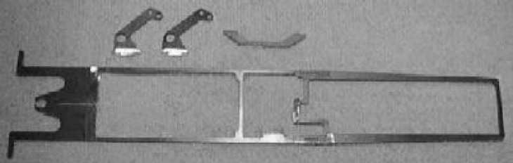
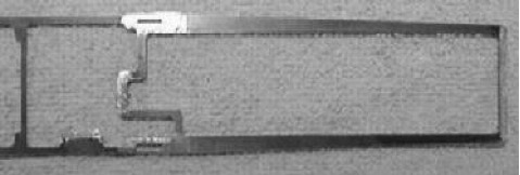
This picture shows, these are the pieces that come in the DRS-SW01 Chassis Kit. They have been trimmed with a Dremel tool, using a cut-off wheel and ready to be pre-tinned. Please note in the photo the areas to be soldered have been lightly ground to remove the chassis bluing, using a Dremel tool.
To set the wheelbase length:
,First put a guide flag, rear axle upright, and front axle holder into the holes/slots in the chassis. Then set a trimmed body down over the chassis, sliding the body fore and aft to line up the rear axle holder with the rear wheel opening. Now look through the front wheel opening, noting where to place the front axle holder.
Now remove the guide and front axle and set the chassis back on the block with the rear axle upright look at the chassis from the top and determine if the front body mounting "horns" need to be trimmed so the body will fit correctly. For this combination of body and chassis it will need to be trimmed back .060". The body should always be installed so that it is flush with the bottom of the chassis.
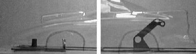
The photo on the left shows the areas of the front of the chassis that are to be pre-tinned. These areas include the front body mounting "horns", and the front axle mounting area. This chassis is being set-up for a Firebird/Camaro body. This choice of body determines the location of the front axle. I have already narrowed the front body mounting horns .060" on each side to allow the use of this body style. The front axle will be mounted almost on the edge to the right. I will leave about .050" exposed on the right side.
The photo on the right shows the areas of the rear of the chassis that are to be pre-tinned. Those areas include the motor mounting area, the axle Pillow Blocks, and the wheelie bar axle mounting location. These areas need to be done regardless of the body used. Only the front axle holder is moved fore and aft to determine wheelbase.

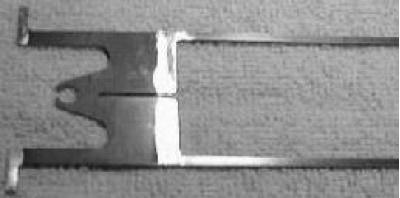
The photo on the left shows I mount my front axle to the front axle holder before I mount the assembly to the chassis. It is much easier to do this before than after. I use my 1" spring clip to hold the front axle holder on the soldering block. Then I center the front axle using a dial caliper and solder in place. For this body style (Firebird/Camaro) I use a piece of DRS-146 Pin Tubing cut to 2.0" long as I am not going to mount the body using the front axle. This will leave enough tube to slide a pair of DRS-148 Front Wheels on the axle and then use DRS-158 Body Pins to hold the wheels on the axle.
The photo on the right shows how I solder the front axle holder in place. I clip the front of the chassis to the soldering block then put a little solder on the chassis and axle holder intersection to one side of the alignment slot. This will allow you to twist the axle holder slightly to align the axle holder. Once the axle assembly is straight solder the opposite side of the alignment slot so you do not loosen the side that you soldered first. Now go back and re-solder the first side.
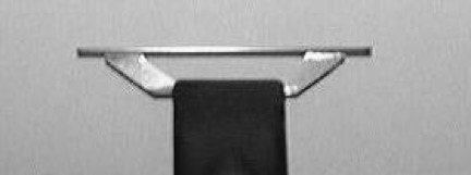
After that is complete it is now time to solder the front body mount. First I slide on two Retainers on to the body mount with the large end of the retainer facing out toward the body. The small end of the retainer should set up on top of the chassis as shown. This will do two things. First it gives a firm support for the body, so the pin tubing does not push itself through the body. Second it raises the pin tubing so it is not so close to the bottom of the body. I know this sounds like much about nothing. This is a very important step however. Those that run on tracks that do not have much shut down area can understand this without much problem. I do not want my pin holes to get loose, or worse, ripped free. I want my body to continue to float correctly in the final round of the big race. This is one reason that when you race us, you will find that our cars stay consistent throughout the rounds of racing. You will win more with consistency that you will with ET/Speed.